
Adjustable feet can correct limited site variation, but an unknown floor is not an approved installation. A long deli-showcase lineup needs a floor survey, one agreed datum and a cabinet-by-cabinet record before joints, trims and services are released. Otherwise a high tile, floor slope or unrecorded step can appear later as uneven glass lines, stressed joints or inaccessible base panels.
The exact plug-in luxury flat-glass deli showcase page lists adjustable feet, a stainless worktop, flat glass, a −1 to 5°C range and 1330, 1960, 2580 and 3830 mm lengths in 960 or 1135 mm depths. It also lists endless splicing for straight or angled lineups. The published page does not state a universal foot-adjustment range, so the installer must obtain the current model drawing instead of inventing one.
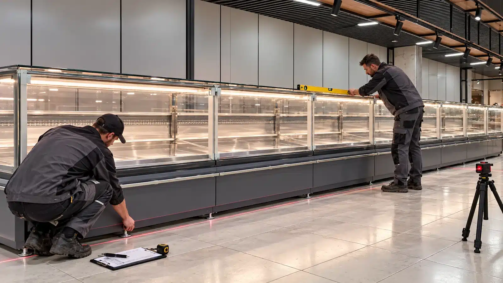
Survey the Floor Before Cabinets Arrive
Mark the final cabinet footprint and service side on the approved plan. Establish a datum with the responsible site party, then take readings at each planned foot position, cabinet joint, end panel and service transition. Record high and low points, floor joints, drains, plinths and changes in finish. A single reading at the centre of the run cannot describe a multi-cabinet line.
Tie every reading to a grid or station number and photograph the measuring setup. State the instrument, calibration or check method, operator and time. If the finished floor is incomplete, label the survey preliminary and identify who must release the final surface before positioning.
The earlier lineup-sequence and counter-joint guide explains how cabinet order and joints affect the run. Add the floor stations to that sequence so the installation team knows which cabinet meets each high or low point.
Confirm the Adjustment Envelope from Current Documents
Obtain the exact model and production drawing for every cabinet. Record the foot locations, accessible adjustment points, approved support condition and any limits stated by the manufacturer. If the available adjustment cannot accommodate the surveyed variation, stop and assign a floor or approved support correction. Extending a foot, adding loose packing or modifying a base outside the documented method is excluded.
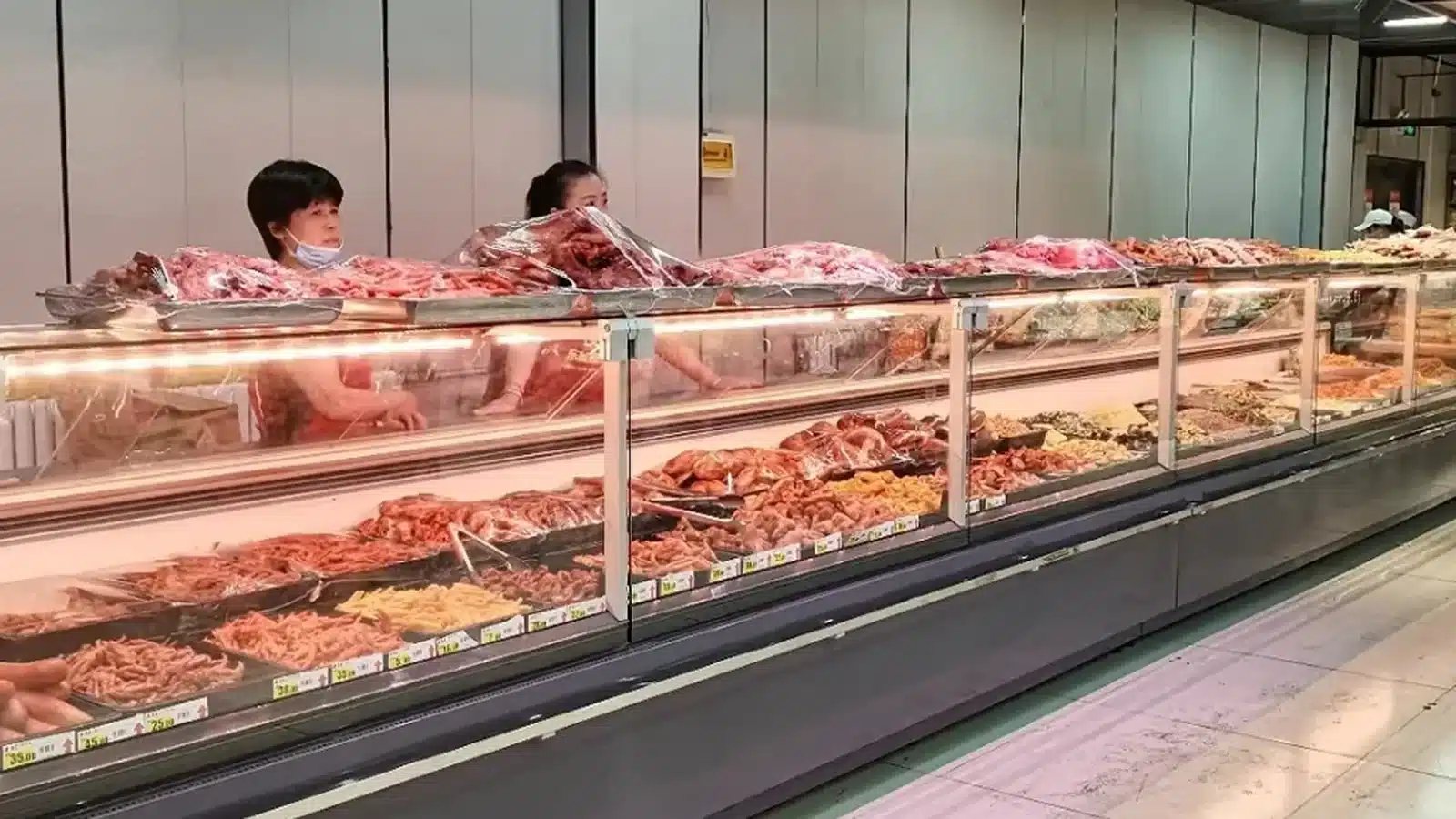
Set the first cabinet against the approved datum and planned front line. Record the initial and final reading at each foot rather than writing only "level." Continue in the agreed sequence and keep temporary protection around glass, panels and floor finishes.
Electrical connection and refrigeration work belong to qualified parties following current documentation. The leveling record should preserve access to base panels, controller and service zones instead of allowing later trades to discover a blocked panel.
Check the Line, Not Just Each Cabinet
After individual cabinets are stable, inspect the complete worktop line, front elevation, glass line and base. Check adjacent cabinets at every joint and record any offset, twist or change in reveal. A cabinet can read level by itself while the lineup still shows an unacceptable joint because the datum, floor or sequence changed.

Follow the manufacturer's current splicing and sealing procedure. Correct the support instead of pulling misaligned cabinets together with joint hardware. Recheck level and joint condition after the run is connected, after nearby floor work and before trims or seal details hide the supports.
Keep food-contact and commissioning checks separate. This handover establishes positioning, support and joint alignment; it does not by itself prove operating temperature, food safety or refrigeration performance.
Close the Handover with an Adjustment Record
The final pack should include the floor grid, datum, instrument record, exact cabinet models, sequence, foot positions, initial and final settings, joint photos, service-access check, deviations and responsible sign-offs. Attach the current model drawings and mark any site correction completed before release.
Photograph the full run from both ends and each joint at the same height. If the floor or cabinet is later moved, use the record as the baseline and reopen the affected stations. This gives the buyer, installer and supplier one traceable explanation of how the lineup was supported.
Related Deli-Showcase Controls
- Compare 960 and 1135 mm flat-glass showcase depth
- Document a deli-showcase digital-controller handover
- Receive and unload a flat-glass deli showcase
Request a Floor-and-Lineup Review
Send the exact model lineup, approved floor datum, high/low-point survey, joint drawing, service-side plan, electrical schedule and site photos through the XCCOLD inquiry page. Ask for the current foot and base details to be confirmed before installation release.